The Goal
I worked with a group of four other students in my robotics class to design and build a quadruped robot dog in the style of Boston Dynamic’s “Spot” robot. It needed to be able to respond to visual inputs, walk, and dance while maintaining resemblance to a real dog. We took inspiration from my dog named Gatorade (yes that’s really his name), and named our robot dog Powerade.

While every aspect of the design, building, and testing required collaboration from each member of the team, we each had our own aspect of the dog which we were particularly focused on.
The four main focuses were:
- Legs (my focus): Program the gait of the dog and ensure stable walking and dancing
- Brain (Antonio Alphonse and Sophie Hankin): Take information from the image processing system and interface with the motor controller board.
- Fabrication (Madeline Fabela): Design and build the structural and aesthetic aspects of the dog.
- Image Processing (Yousef Abdo): Use openCV python code to recognize objects and send signals to the brain.
My focus was getting the dog to walk and dance, which had 5 main aspects:
- Speccing out motors.
- Planning a smooth step path.
- Using Inverse Kinematics to calculate the angles to set each leg.
- Coding the motor controller board to send the angles to the motor at each joint when prompted by the “brain” microcontroller.
- Testing and iterating to ensure a stable gait
Pre-Build Planning and Calculations
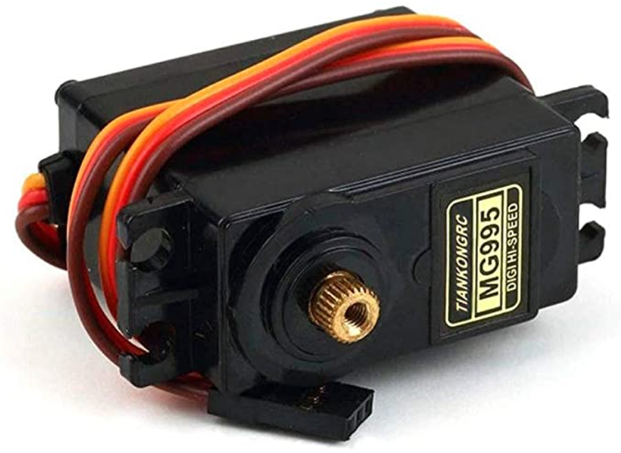
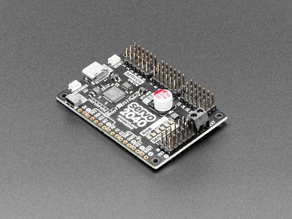
Before we dove into designing and building the dog, we had to decide what motors and boards to use. After coming up with the approximate size we wanted the dog to be, we did some simple calculations to help us decide what torque was necessary to provide stability. We picked a set of high torque servos and a Servo 2040 motor controller board for maximum positional control.
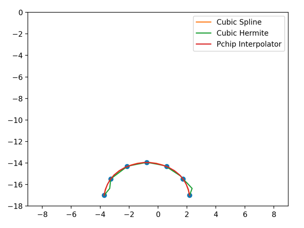
I got to work on planning the path of the motors for the dog’s walk and dance motions. I first came up with a set of seven points I wanted the foot to be at at different times during a step. I used a python script to generate multiple splines given those input values, and picked the one I thought was the smoothest. I then fed those position values from the spline into a Matlab script I wrote, which uses the law of cosines to calculate the angle of each joint given an input x-y position and the length of each leg.
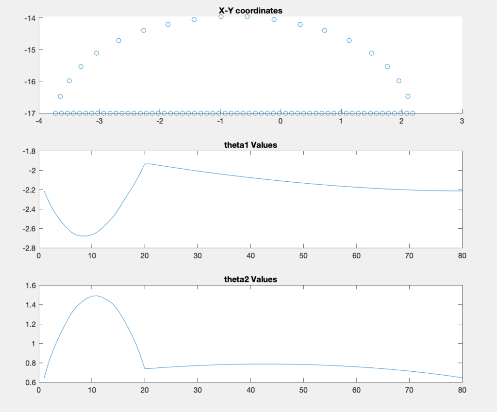
I then wrote a script in python to plot a digital twin of what the step would look like with the angles I calculated, as a sanity check that my code worked and to make sure the step looked natural and smooth.
Initial Prototype: the “Puppy”
In order to get a better sense of the challenges at hand, we decided to first create a smaller version of our dog to test our ideas while we were waiting for parts to arrive. Madeline designed and lasercut a small wooden body and legs which could be driven by microservos. This was my opportunity to test out the gait I had programmed.
As you can see, the steps are short and unstable. When we weren’t holding up the battery pack, the dog would fall almost as soon as the legs lifted off the ground. I realized that in order for the dog’s walk to be stable at a higher weight, only one foot could be lifted from the ground at a time instead of two. This meant that each leg would be out of phase from the others, increasing the complexity of my code.
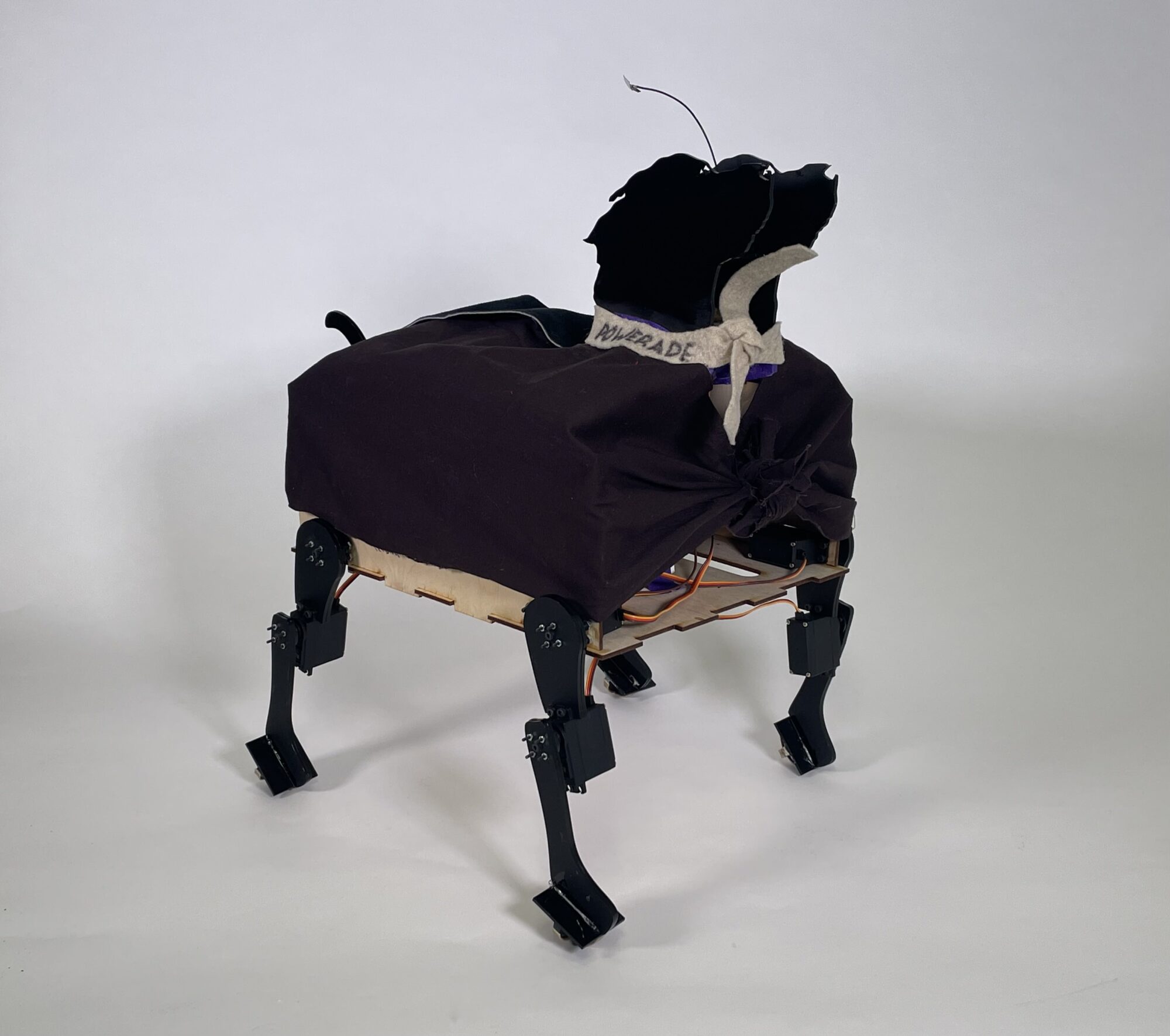
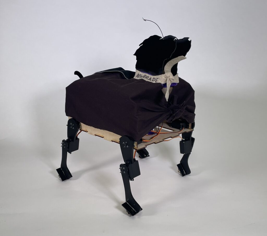
Scaling Up
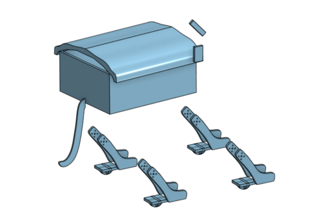
Once we had access to the higher torque servos, we began to scale up our design. Madeline did an excellent job designing a structure which could be built entirely out of lasercut materials. One of the goals of the project was to consider the sustainability of our design, which is why we chose to avoid 3D printed parts. The legs were made out of two layers of 3mm acrylic, and the body was made of 3mm birch. We used black fabric to cover the body to hide the electronic components and mimic Gatorade’s majestic black fur.
Debugging and Refining the Walk
Now that we had a fully grown dog, I had a chance to test my walking code and ensure the dog was balanced at every point in the walking cycle. This proved to be a serious challenge. The dog would become unstable and fall as soon as one leg was lifted off the ground.
I changed the leg paths, step sequence, and center of gravity multiple times to no avail. The dog would always lose balance and fall after one or two steps. Finally I realized there were two changes we needed to make in order to stabilize the dog.
- More weight needed to be added to the body of the dog. In its skeletal form most of the weight of the dog was in the servos attached to the legs, so when the legs swung around it would destabilize the dog and skew the center of gravity from where I expected it to be.
- The steps needed to be faster. I realized in the time frame we were given to complete the project it would be very challenging to find a step path which would keep the dog stable 100% of the time. If the steps were shorter and faster the dog would only be unstable for short amounts of time making the dog less likely to fall. This would make the motion less of a walk and more of a slow shuffle but that was a sacrifice we were willing to make.
Image Processing
We then created an image processing system which was effective at recognizing objects. Yousef made two planks of wood with different patterns on them, one to signal the dog to walk and the other to signal the dog to sit. We fed dozens of images of the two wood planks into the EdgeImpulse machine learning software which output OpenCV code which we uploaded onto the camera board. We mounted the camera board on the head and attached it to a microservo so it could look left and right.
The Brain
To tie everything together, we devised a system where an RP2040 would asynchronously listen for an MQTT message from the camera chip, and send the appropriate signal to the motor controller board. We also built an Adafruit dashboard which could also communicate through MQTT with the brain chip if we wanted to control the dog manually. We initially ran into an issue where our motor controller board had no wifi capabilities or serial communication pins. I came up with an idea to use the boards analog sensor pins to read a voltage from the brain boards digital output pins. We assigned each pin to an action, walk sit, and dance and set the voltage to high on that pin when the command was received from either the camera or the dashboard.
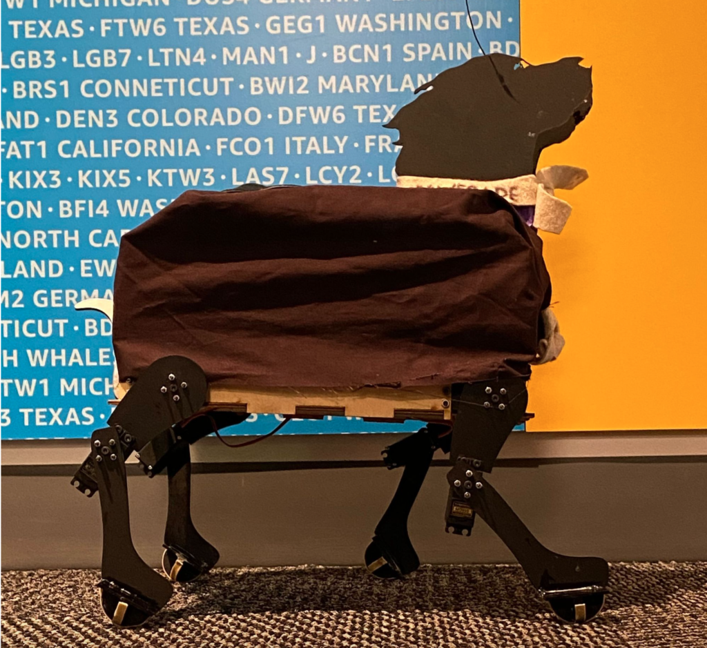
The Final Product
When our project was finished we presented our final product at the Amazon Robotics office in North Reading, MA. Below you can see a vide of our dog recognizing the wooden slats and alternating between a sit and a walk motion:
I learned a lot during this project, from debugging skills, to geometric calculations, to fabrication, to teamwork and persistence. I’m very proud of my group and what we were able to accomplish. I think we all did a great job executing on our personal responsibilities while also helping everyone else with their respective roles when needed.
If we had more time to work on the project I would have loved to do more iteration on the walk gait. As you can see from the video the forward progress when the dog is walking is quite slow, and I would want to increase the horizontal length of the steps in order to generate more forward momentum.
Github Repository: