Introduction:
For my Senior Design project I teamed up with three other Tufts students and worked under the guidance of an engineer at NASA’s Armstrong Flight Research Center to develop a proof-of-concept design for a lifting body which would be used to collect data on Uranus. Our goal was to prove it is possible to build a probe in the shape of a lifting body which meets all of the specifications required to survive launch conditions and carry sensing equipment, while maintaining the mass characteristics and geometry necessary for stable flight.
This project was a great experience in accomplishing a broad scope engineering problem with a small team. My main responsibilities as a member of the project team included:
- Designing the internal structure in Solidworks.
- Running Frequency Response simulations.
- Setting up and running random vibration dynamic simulations.
- Placing internal components to optimize Moments of Inertia and Center of Gravity
Background Information
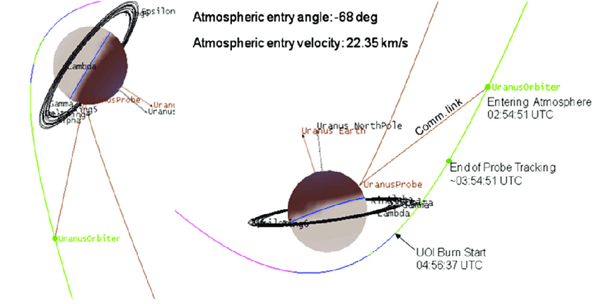
In the coming years, NASA plans to develop a probe to drop into the Uranus atmosphere to collect environmental data at different altitudes. This mission, known as Uranus Orbiter and Probe (UOP), was recommended by the National Academy of Sciences and will help NASA better understand other ice giant planets like Uranus. The probe will only be able to transmit data for 40 minutes before the satellite loses contact with the probe. Traditional atmospheric probes use parachutes, but NASA has determined that a parachute would slow down the probe too much in the lower, denser part of the atmosphere. If a probe were dropped without a parachute, it would fall too quickly in the upper part of the atmosphere to fully characterize the different atmospheric layers.
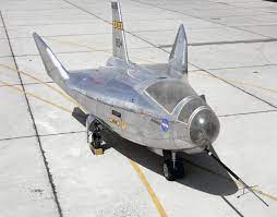
Our mentor, John Boldyski, proposed a solution in which the probe would be in the shape of a lifting body. Lifting bodies were heavily researched by NASA in the 1960s and 1970s in order to learn more about creating smaller aircrafts. They are aircrafts with large central bodies and very small wings, designed so that they generate lift passively without using wings. If the probe is designed like a lifting body, it will be able to change its angle of attack at different altitudes in order to manipulate its drag and lift and hold a consistent fall rate.
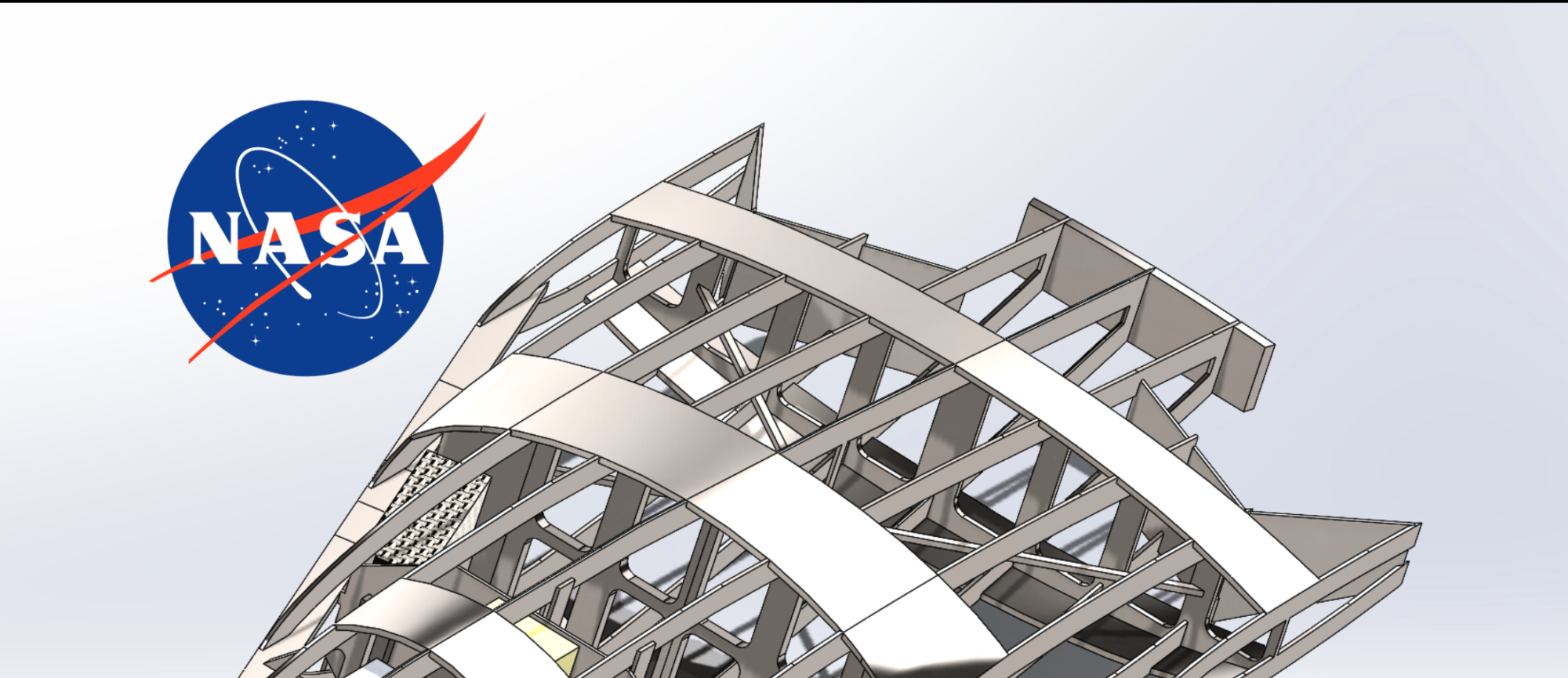
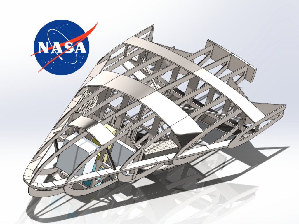
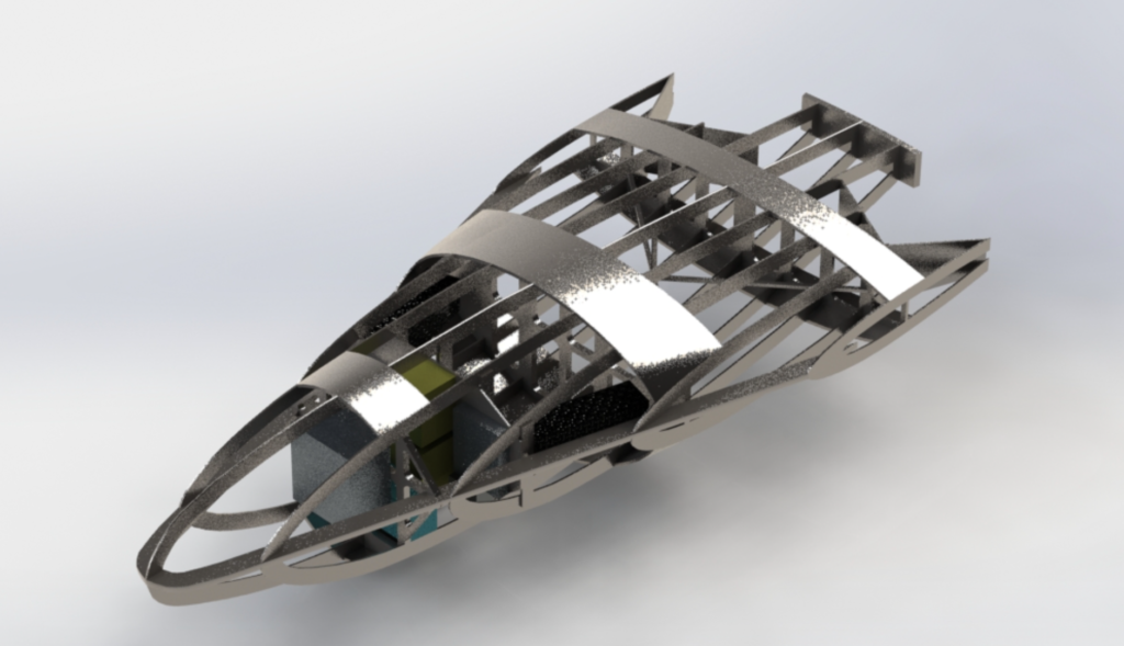
Our part in this project was to choose an existing lifting body design and use its OML to create an internal structure that would fit the vehicle. Our solution is based on the HL-10 lifting body, and it delivers the internal structure and the layout of scientific instruments inside. Our design minimizes the total weight of the probe since the cost of each additional pound at launch can be over $36,000. The internal layout of the probe also ensures a proper center of gravity (COG) and moments of inertia (MOI) so that the lifting body flies correctly, which means that the scientific instruments must be placed correctly in order to ensure proper distribution of mass. This lifting body design will also allow for higher data transmission than a traditional probe, as the signal to the satellite collecting the data can be more focused and thus stronger.
User Needs and Engineering Specifications:
Our group met with our mentor and other NASA Engineers to determine a comprehensive list of user needs and accompanying engineering specifications our design must meet. We then created a Quality Function Deployment diagram to organize and prioritize the different user needs.
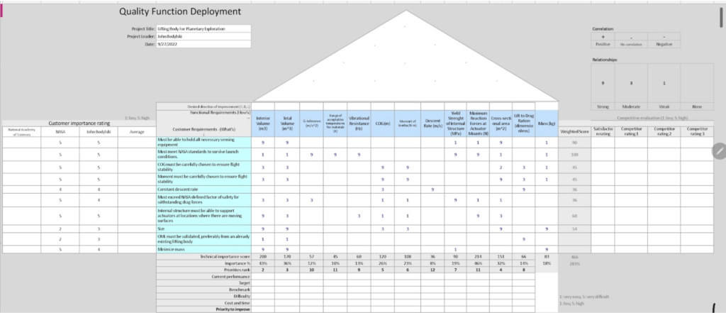
We determined that the most important user need is that the structure must not yield under launch conditions. The process which would induce the most stress on our probe during its mission would be the random vibrations during launch. The probe would experience up to 19 GRMS (Gs root mean square) of acceleration during launch, so if it can survive the stresses of launch it is highly likely to be robust enough to survive the rest of the mission.
Ideation and Initial Planning
We chose to model our outer geometry after the Northrop HL-10, a lifting body which was extensively tested by NASA in the 1960s. Since the scope of our project was designing the internal structure, using a pre-existing outer geometry was recommended by our mentor.
We began by researching designs for aerospace support structures, including common geometries, fixtures, and materials. We then came up with ten different possible designs for the internal structure of the probe and evaluated them based on how they would be able to meet our user needs. Using a decision matrix we down-selected until we had two possible design concepts and made initial models of each concept.
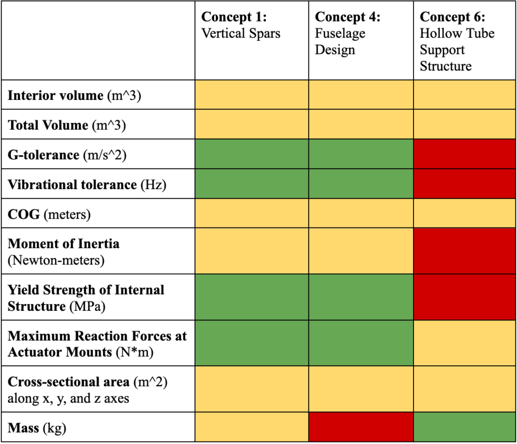
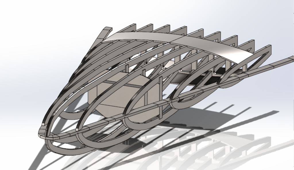
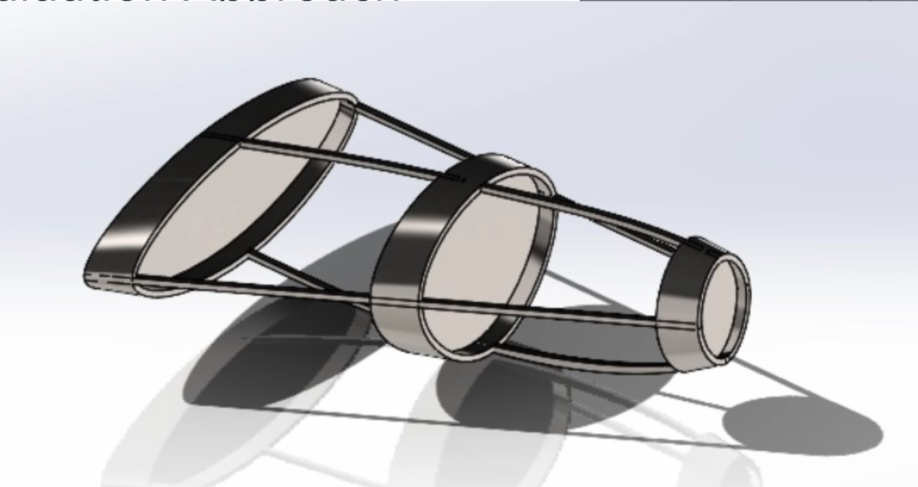
We made the ultimate decision to combine our final two designs to incorporate the advantageous aspects of each design. I was tasked with creating the model of this combined design in Solidworks.
Frequency Studies
In order to design for vibrational stress resistance, we ran static frequency studies in Solidworks to model the modes of our geometry. This provided a quick and easy way to visualize where our structure was susceptible to vibrational stresses and what the resonant modes are. We wanted to avoid having modes at very low frequencies (<50 Hz) and wanted to avoid different parts of the geometry having the same resonant frequencies which could compound on each other. Shown below is a visualization of one of the modes of a frequency study run on one of the earlier versions of our design:
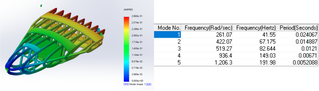
We used these results to quickly iterate on our design multiple times and hone down on a design which is sturdy enough to limit vibrational displacement while minimizing weight.
Boundary Conditions
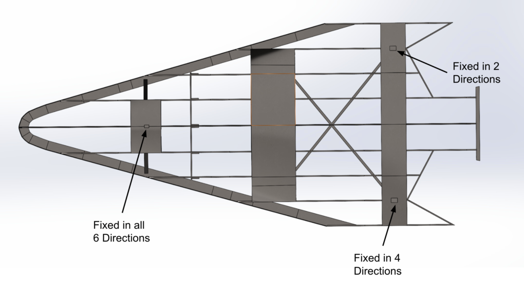
In order to use boundary conditions which most accurately model how the structure will be attached to the launch vehicle, we consulted NASA simulation experts. We were advised to have three mounting points on bulkheads, and to keep the center of gravity in the middle of all three. When a vehicle is launched into space, its mounting setup has to allow for thermal expansion and contraction. In order to replicate this we had one mounting point fixed in all 6 degrees of freedom, one fixed in 4 degrees of freedom, and one fixed in only 2 degrees of freedom.
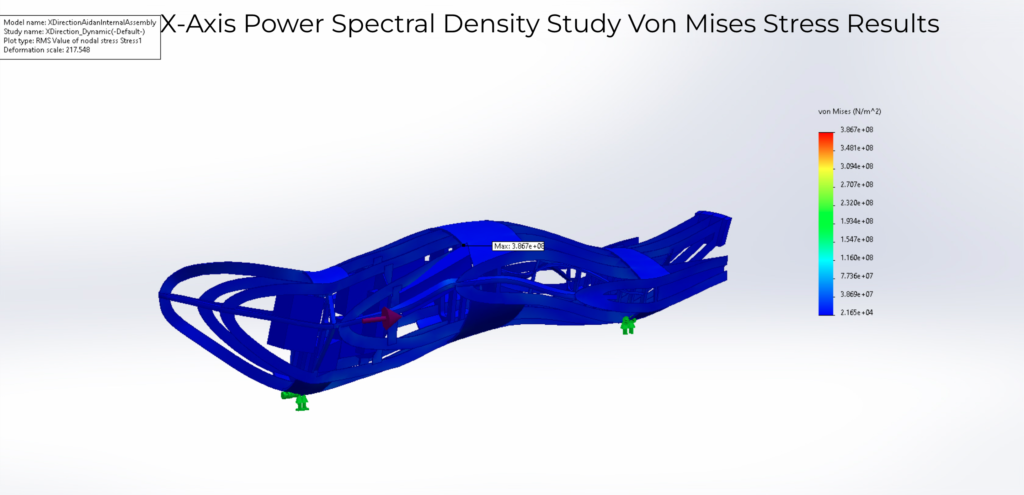
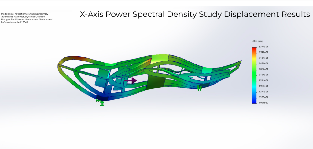
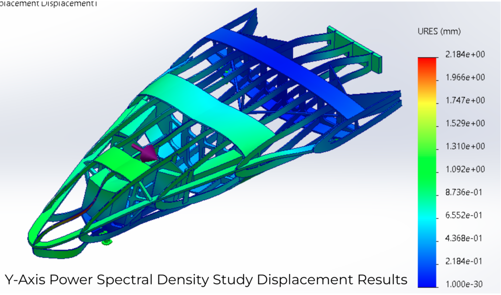
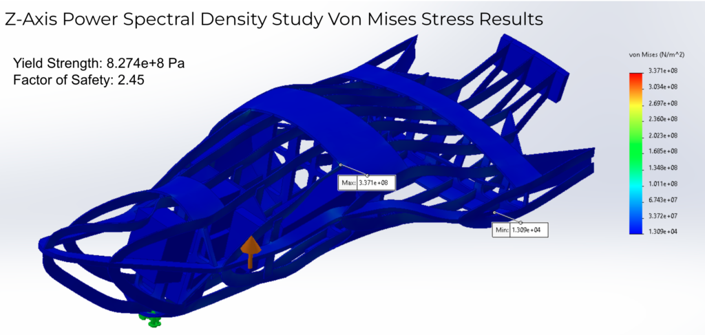
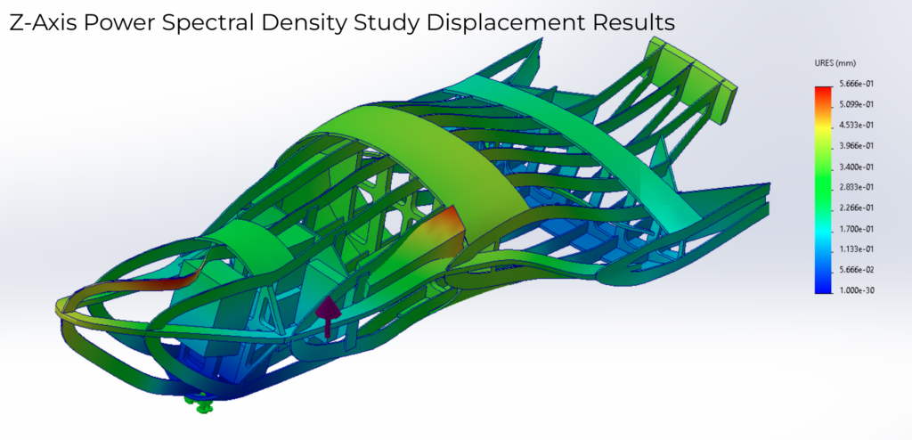
Random Vibration Power Spectral Density Study
We used a Random Vibration Study with a Power Spectral Density curve as the input base excitation to simulate the stress and displacement caused by random vibration during launch. The PSD curve we used was obtained from a NASA environmental testing document. We used the “D curve” shown in the figure below as it represents the conditions experienced in a large rocket during launch.
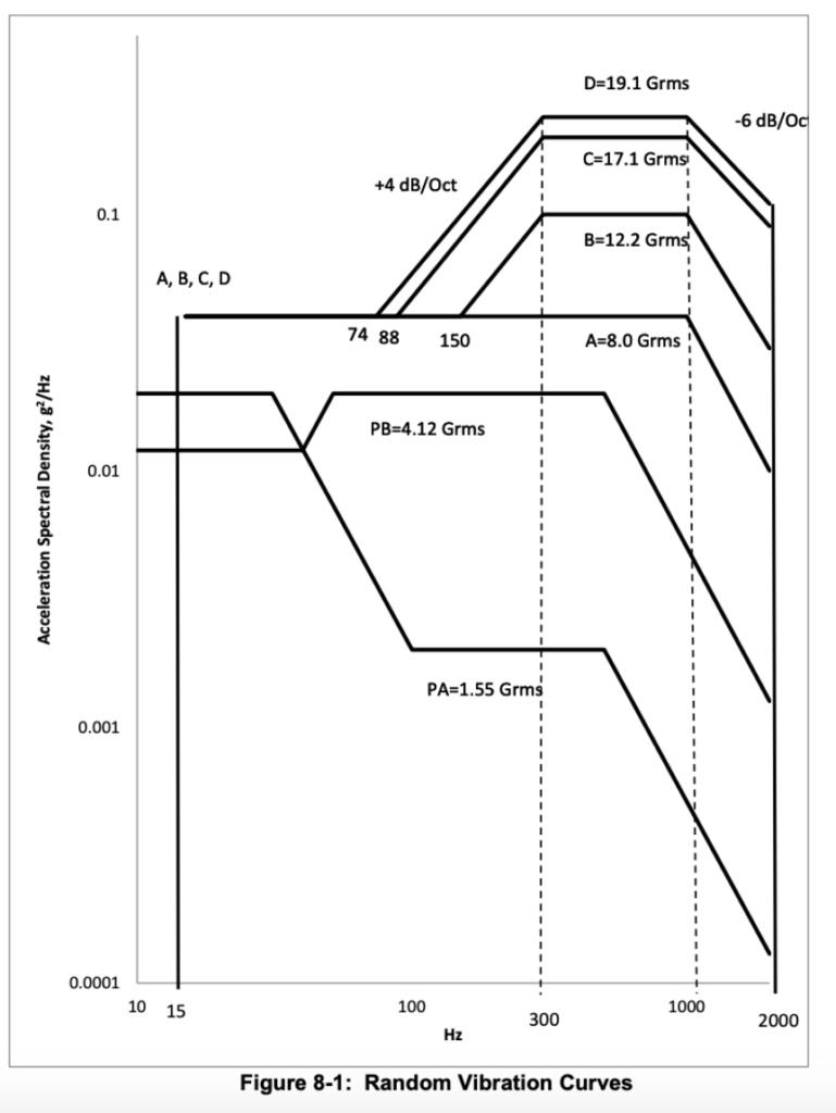
After inputting curve D as the base excitation for the study, we multiplied our input by a factor of 3 to ensure we would be accounting for 99.7% of random vibrations experienced during launch (3).
We ran random vibration tests with the D curve as the input in all three directions (x,y and z), with the same boundary conditions as the frequency studies. We found that the maximum Von Mises stress experienced was well below the yield strength of our chosen Titanium alloy in all three directions, with the lowest factor of safety being 2.45. We found the maximum deflection in our three studies to be 2.18 millimeters in the Y direction.

Material Selection
The material selected for our design, Ti-6Al-4V Solution Treated and Aged, was chosen for its strength to weight ratio as well as its manufacturability. It is weldable and machinable, which is useful because in order to manufacture our structure the parts would be cut out of sheet metal or CNC milled and then welded together.
The material we chose was validated by the Metallic Materials Properties Development and Standardization (MMPDS), which is a reliable source for accurate materials data, to meet our specified temperature, stress, and manufacturability requirements. This alloy of Titanium has a yield strength of 1100 MPa and a fatigue strength of 750 MPa at 10^6 cycles, and a temperature range of -196C to 399C, which encompasses the required range of -196C to 128C.
Mass Properties
Once we were confident the structure could withstand all stressed with. a high enough factor of safety, we needed to make sure the mass properties were conducive to stable flight. The center of gravity needed to be equal to or in front of the center of lift, and the moment of inertia in the X direction needed to be greater than or equal to the moment of inertia in the Y direction. These properties in sure that the flight of the lifting body will be stable and controllable.
I modeled simplified versions of the sensing equipment the probe would need to carry with accurate masses and volumes. I then placed the equipment such that the center of gravity was in the correct place, and then spread out the equipment away from the x axis to increase the moment of inertia about the x axis.
Reflection
I had an amazing time working on this project. My team members and mentor were great and I’m proud that we were able to meet our initial goals for the project. Some of the key skills I improved from the project include:
- Understanding Aerospace Principles: I learned about many of the challenges associated with designing a flying object including weight minimization, controlling moments of inertia and designing for manufacturability.
- Computer Aided Design: I greatly improved my proficiency in Solidworks as I was the group member who was responsible for creating the model of our design in CAD.
- Collaboration and Project Management: As this was a semester long project, lots of planning and collaboration was required to accomplish our goals. We used methods such as a team contract and Gantt charts to hold ourselves accountable. We also had weekly meetings with our mentor and would often send email updates, which improved my professional communication skills
- FEA Simulations: I gained valuable experience in designing and running FEA tests to simulate real world environments. I learned about the importance of having accurate boundary conditions in these studies how to interpret results.
While I believe the project was a success, I still think there are areas we could improve. If we had more time, I would have loved to model the surfaces (flaps) and fins of the lifting body. This way we could calculate the stresses caused by drag when the surfaces are fully angulated and do static tests on our structure to be sure it could withstand those stresses. I would have also liked to validate our FEA tests by running benchmark tests and comparing the results to studies done in the real world. This way we could be confident our setup is correct and our software is making accurate calculations.
In summary, working on a senior design project with NASA to design the internal structure of a lifting body taught me about aerospace principles, project management, CAD and simulations. These are all valuable skills that can be applied to other engineering projects and professional pursuits.