
Overview
The Chessboard consists of the following:
- 4 Custom PCBs each with 16 Hall-Effect sensors and an analog multiplexer
- 3D printed chess pieces with magnets enclosed
- Custom Python script which uses the Stockfish chess engine running on a Raspberry Pi to
- Keep track of moves
- Provide feedback on quality of each move
- Suggest opponent moves if you choose to play against the computer
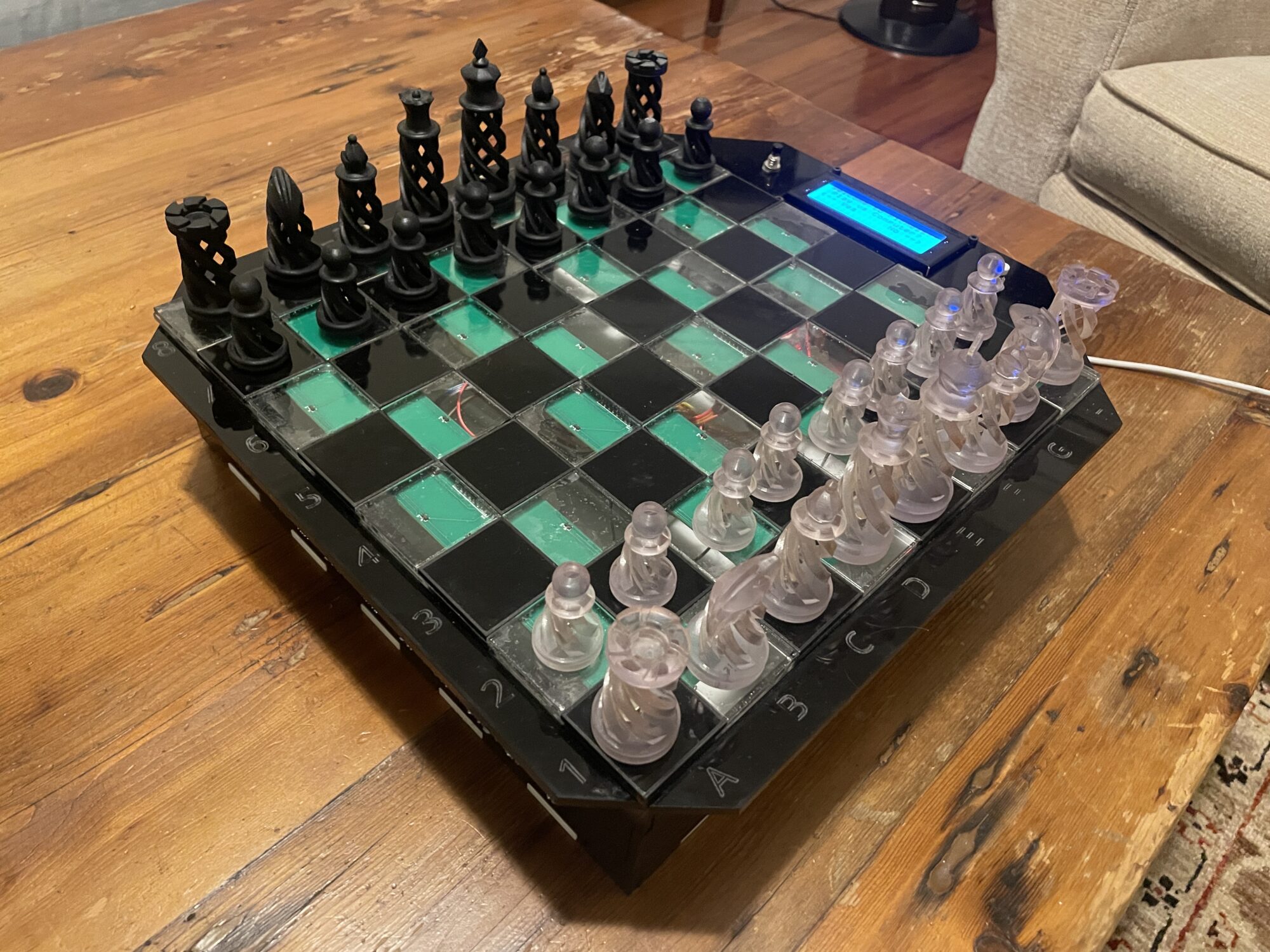
- Lasercut acrylic case and chessboard
- LCD screen and buttons for user feedback
Motivation
For the past few years, I’ve picked up an interest in chess and have found myself challenging faceless foes on chess.com quite often during my free time. However the allure of playing on a two dimensional screen could only last so long, and while I was working at Formlabs I took advantage of my access to the prototype Form4 resin 3D printers to print a real life chess set and lasercut a chessboard out of acrylic.
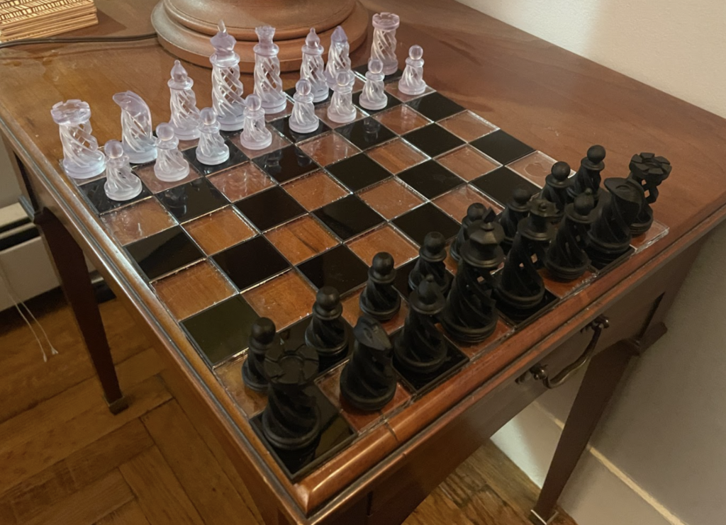
While the chessboard did make for a nice accent piece in the living room, unfortunately none of my friends play chess and my new toy sat in the corner collecting dust. So like any good engineer, instead of making new friends who play chess I decided to solve the problem with code and electronics.
Sensors: Ideation and Initial Prototyping
The biggest challenge off the bat was I/O. Since there are 64 squares on a chessboard, there needed to be 64 sensors and therefore 64 signals and/or lines of communication the Raspberry Pi has to read.
Click to see all of the piece sensing ideas I considered and why I didn’t choose them
RFID tags and sensors:
- This would be a straightforward way to know where each individual piece is, however I read that having multiple RFID tags in close proximity could cause issues, and the prospect of dealing with 64 lines of I2C communication hurt my puny MechE brain.
LED shining up from each square with a photoreceptor to read the specific hue of paper glued underneath each piece:
- This was a fun idea however it runs into similar issues as the previous idea and would add a lot of complexity to the PCB design.
Computer Vision:
- This was probably the most practical solution to this issue but who wants a webcam looming over their chessboard.
Binary piece sensing with pressure switches or reed switches:
- I figured you wouldn’t have to identify each unique piece as long as you know the starting position and can follow each move. Having a digital on/off signal instead of an analog signal or line of communication (I2C, SPI) would make my life so much easier,
- However this method runs into a fundamental problem:
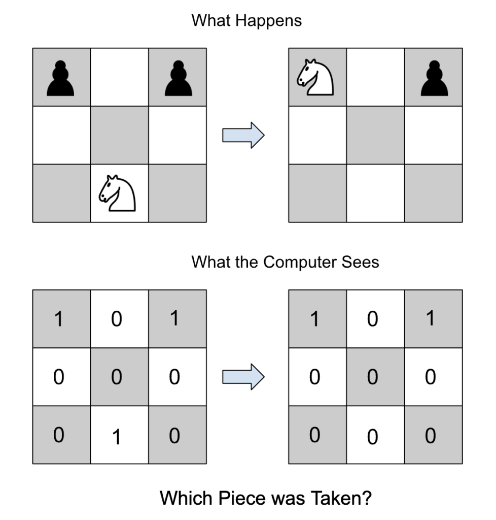
- Unless I wanted to be continuously tracking the status of the board (which could get messy because what if the user picks up a piece and then changes their mind) I would need a way to at least know the difference between the white and black pieces.
Photoresistors
- Since the white pieces were printed with clear resin and are translucent, I figured that having a photoresistor under each square would allow me to sense the change in light between an empty square, a square with a translucent piece, and a square with an opaque piece on it
- I bought photoresistors and prototyped this idea, however I found it to be too susceptible to shadows and different light conditions.
I chose to use bipolar analog signal hall-effect sensors under each square and have each piece contain a magnet. White and black pieces would have opposite magnetic poles facing down so the two colors of pieces could be differentiated.
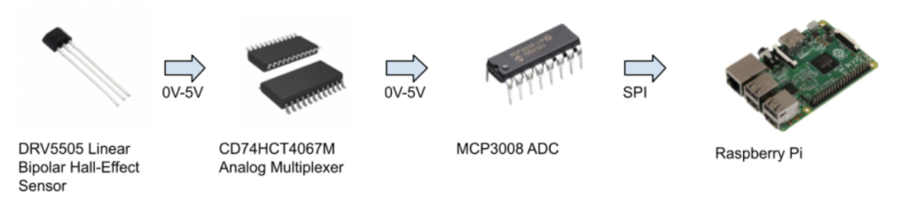
When no magnetic field is present, the sensor outputs half of the input voltage (2.5V in this case). So if the sensors output goes above or below a certain threshold you know a piece is on that square and can determine which color piece it is. Since the ADC I chose only has 8 inputs I used an analog multiplexer to toggle between 16 different sensors with the same input line.

Initial testing of the sensors with an Arduino
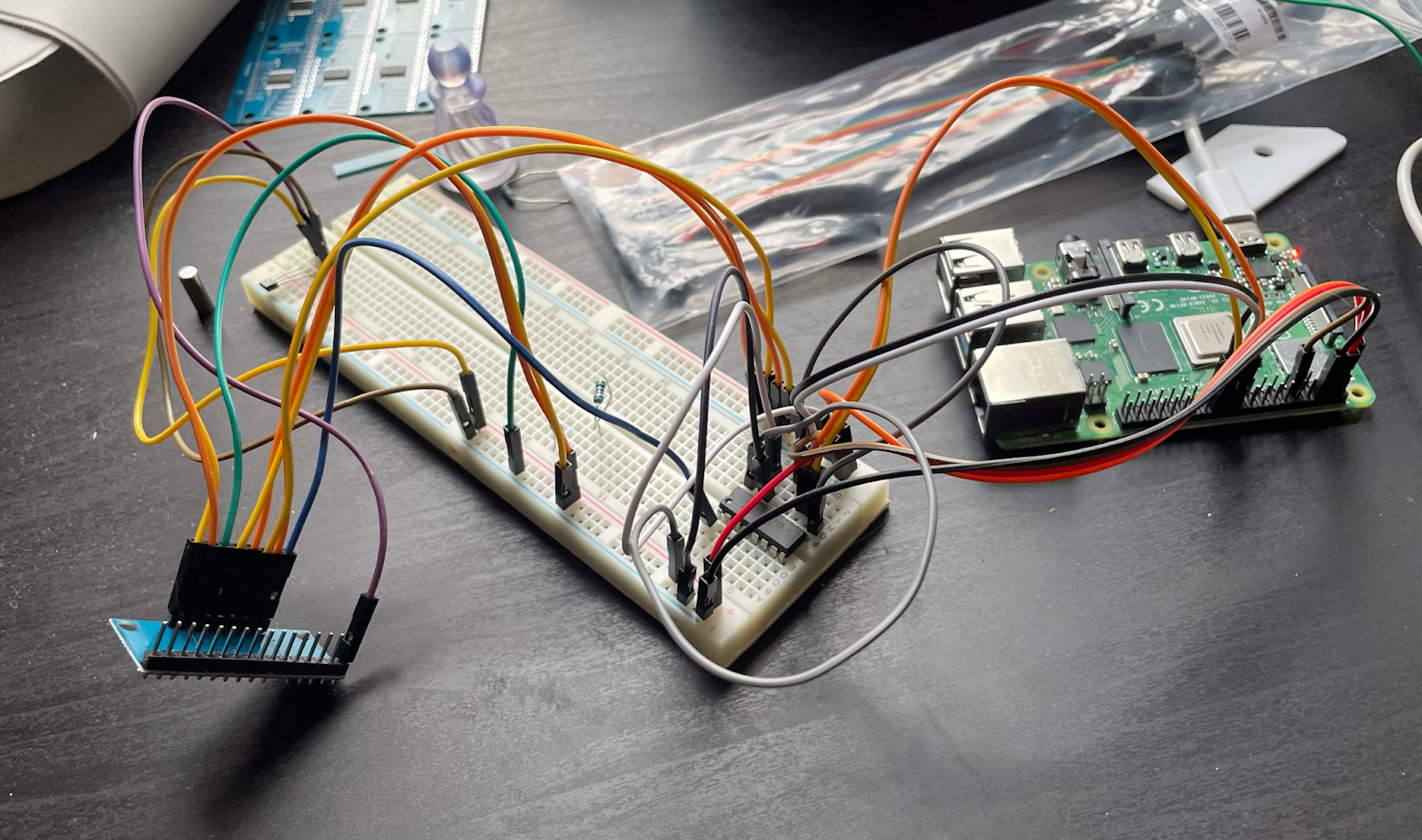
Incorporating the multiplexer, ADC, and raspberry Pi
PCB Design
Instead of one big PCB with 64 sensors, I decided to make 4 PCBs each with 16 sensors and one multiplexer. This would make the order slightly cheaper and if I broke one of them or there was a manufacturing defect it would be easier to replace.
I had JLPCB recommended to me as a cheap way to get PCBs fabricated and assembled, and I was able to use their free browser based PCB design software called EasyEDA to create the BOM and gerber files while being able to see what parts they had in stock for assembly.
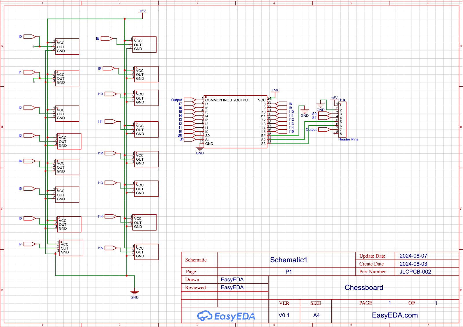
The circuit was relatively simple, and my prototyping allowed me to have confidence in my circuit design


Using the footprint layout tool I could precisely place the sensors to be under the center of each chessboard sqaure
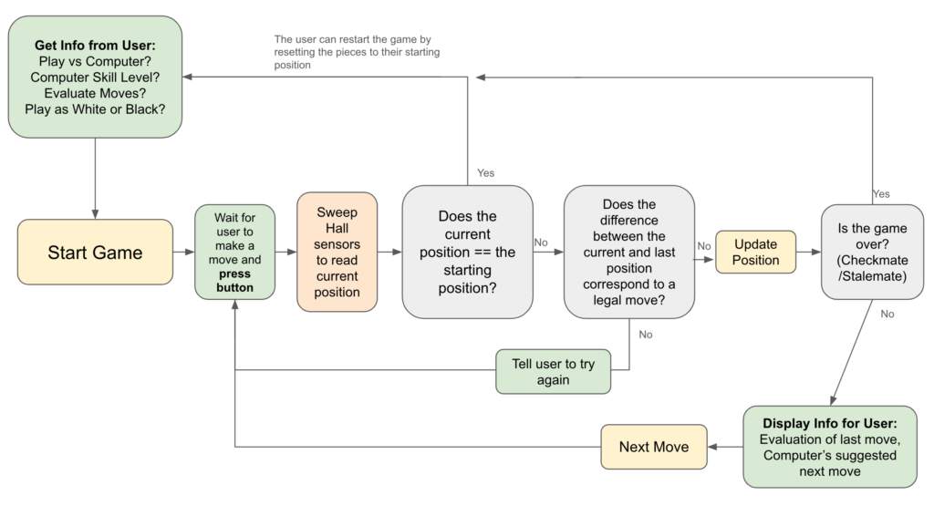
The Code
I used the stockfish python module to keep track of moves during a game and evaluate the position after each move. Stockfish is the most powerful chess engine in the world, and this module allows you to access it via a python script. With some tweaking of parameters to account for the limited RAM available on my Pi I was able to get the module up and running and write a script which facilitates a game of chess.
Code Overview:
Github:
https://github.com/abeckski/pichess
The Enclosure
I lasercut the enclosure out of acrylic and used acrylic weld to join the sides together. I used an LCD2004 display and 2 buttons for user input and feedback
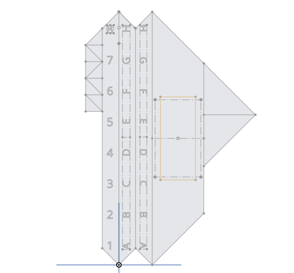
I used Onshape to design the DXF to cut out of acrylic
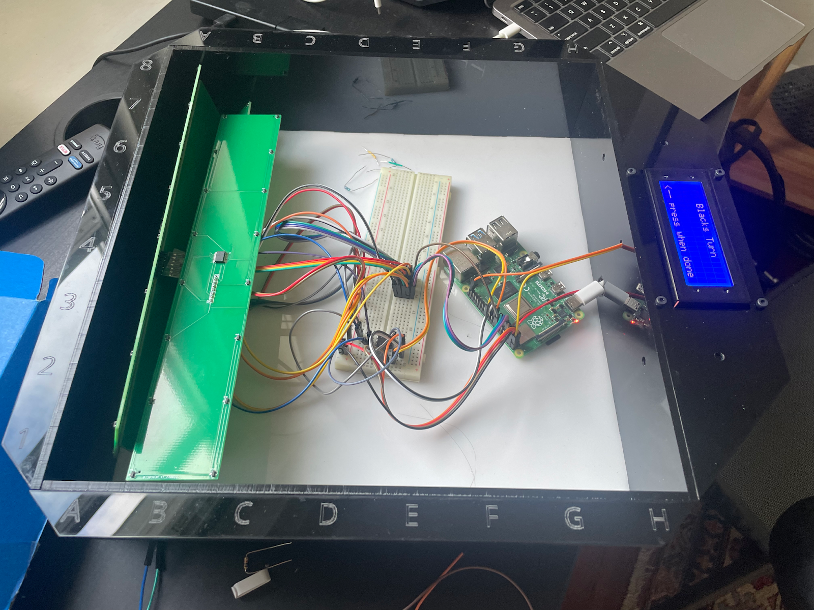
I designed the enclosure such that my original chessboard could be dropped on the top and the sensor boards would be adhered to the bottom
Final Product
What I Learned
- Electronics
- Becoming familiar with different sensors, multiplexers and ADCs
- I2C and RPI communication
- PCB design
- Code
- Practice designing and coding a state machine
- General Python skills
- General Engineering
- Debugging and Integration skills
- User-focused design
- Confidence to learn new skills and step out of my comfort zone 🙂